# QuadRemesh
##  QuadRemesh
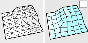
The QuadRemesh command quickly creates a quad mesh with optimized topology from existing surfaces, meshes, or SubDs. It uses a unique algorithm to generate manageable polygon meshes, ideal for rendering, animation, CFD, FEA, and reverse-engineering.
### Options
#### Target Edge Length
Sets the approximate edge length of the output mesh.
* This setting is scale dependent. The resulting face count increases with object scale.
* Re-meshing would fail if the target edge length is set too large for the object size.
#### Target Quad Count
Sets the approximate face count of the output mesh as a goal for the algorithm.
* This setting is scale independent. An input object in different scales produces a similar face count.
**Adaptive Size (0-100)**
Set 0 to get a minimal number of quads and uniform sizes. A value above 30 will diminish your control of getting a smaller number of quads. Higher values result in smaller quads in high curvature areas. Set 100 to keep more details.
| | **0** | **100** |
| -------------------------------- | ----------------------- | -------------------------- |
| **Face shape** | As square as possible | Varies in width and height |
| **Face size** | Similar | Varies |
| **Face density** | Uniform | Higher at details |
| **Fit to original shape** | Less | More |
| **Respect to target face count** | More | Less |
| **Risk** | Topology irregularities | More faces |
**Adaptive Quad Count**
#### Use Surface Edges (Polysurface/Extrusion only)
Specifies if meshes edges will be created along the sub-face boundaries on the input object.
* **Off**
Ignores sub-face boundaries.
* **Smart**
Retains sub-face boundaries except for the ones being determined as meaningless by the algorithm. This is usually the best choice.
* **Strict**
Retains all sub-face boundaries.
#### Symmetry Axis: X /Y /Z
Select to perform symmetrical re-meshing across the X, Y, or Z central plane of the object's bounding box. Multiple axes can be selected. It only makes sense for symmetrical objects and when the correct symmetrical plane is selected.
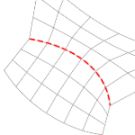
#### **Guide Curves**
The quad re-meshing algorithm will try to place edge loops or edge rings along guide curves. Guide Curves can be used to define more details, or simply influence the direction of quad re-meshing in a region. Guide curves must be projected onto the input object to have an effect. Click Select Curves to select guide curves.
* **Curve Influence**
These options control how guide curves affect the final quad mesh.
* **None**
No effect on the result.
* **Approximate**
Adjusts the general direction of the quads by influencing their natural flow. The guide curves have a weak effect on the result.
* **Create Edge Ring**
Orients the crossing edges perpendicular to the guide curves. The guide curves have a stronger effect on the result, but edge rings may not follow guide curves exactly.
* **Create Edge Loop**
Places edge loops along guide curves. The guide curves have the strongest effect on the result.
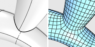
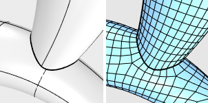
#### **Detect Hard Edges**
Uses a 30-degree break angle threshold to divide the quad mesh with hard edges (creased edges). If the break angle between two adjacent faces is larger than 30 degrees, a hard edge loop will be added.
*Turn this option off if...*
\- You do not want hard edges on the quad meshes.
\- The input mesh is disorganized to avoid adding unintended hard edges.
For more information, please refer to the [Rhino documentation](https://docs.mcneel.com/rhino/8/help/en-us/commands/quadremesh.htm#\(null\)).
---
# Agent Instructions: Querying This Documentation
If you need additional information that is not directly available in this page, you can query the documentation dynamically by asking a question.
Perform an HTTP GET request on the current page URL with the `ask` query parameter:
```
GET https://docs.rhinoartisan.com/commands/subd/edition/quadremesh.md?ask=
```
The question should be specific, self-contained, and written in natural language.
The response will contain a direct answer to the question and relevant excerpts and sources from the documentation.
Use this mechanism when the answer is not explicitly present in the current page, you need clarification or additional context, or you want to retrieve related documentation sections.
QuadRemesh
The QuadRemesh command quickly creates a quad mesh with optimized topology from existing surfaces, meshes, or SubDs. It uses a unique algorithm to generate manageable polygon meshes, ideal for rendering, animation, CFD, FEA, and reverse-engineering.
### Options
#### Target Edge Length
Sets the approximate edge length of the output mesh.
* This setting is scale dependent. The resulting face count increases with object scale.
* Re-meshing would fail if the target edge length is set too large for the object size.
#### Target Quad Count
Sets the approximate face count of the output mesh as a goal for the algorithm.
* This setting is scale independent. An input object in different scales produces a similar face count.
**Adaptive Size (0-100)**
Set 0 to get a minimal number of quads and uniform sizes. A value above 30 will diminish your control of getting a smaller number of quads. Higher values result in smaller quads in high curvature areas. Set 100 to keep more details.
| | **0** | **100** |
| -------------------------------- | ----------------------- | -------------------------- |
| **Face shape** | As square as possible | Varies in width and height |
| **Face size** | Similar | Varies |
| **Face density** | Uniform | Higher at details |
| **Fit to original shape** | Less | More |
| **Respect to target face count** | More | Less |
| **Risk** | Topology irregularities | More faces |
**Adaptive Quad Count**
#### Use Surface Edges (Polysurface/Extrusion only)
Specifies if meshes edges will be created along the sub-face boundaries on the input object.
* **Off**
Ignores sub-face boundaries.
* **Smart**
Retains sub-face boundaries except for the ones being determined as meaningless by the algorithm. This is usually the best choice.
* **Strict**
Retains all sub-face boundaries.
#### Symmetry Axis: X /Y /Z
Select to perform symmetrical re-meshing across the X, Y, or Z central plane of the object's bounding box. Multiple axes can be selected. It only makes sense for symmetrical objects and when the correct symmetrical plane is selected.
#### **Guide Curves**
The quad re-meshing algorithm will try to place edge loops or edge rings along guide curves. Guide Curves can be used to define more details, or simply influence the direction of quad re-meshing in a region. Guide curves must be projected onto the input object to have an effect. Click Select Curves to select guide curves.
* **Curve Influence**
These options control how guide curves affect the final quad mesh.
* **None**
No effect on the result.
* **Approximate**
Adjusts the general direction of the quads by influencing their natural flow. The guide curves have a weak effect on the result.
* **Create Edge Ring**
Orients the crossing edges perpendicular to the guide curves. The guide curves have a stronger effect on the result, but edge rings may not follow guide curves exactly.
* **Create Edge Loop**
Places edge loops along guide curves. The guide curves have the strongest effect on the result.
#### **Detect Hard Edges**
Uses a 30-degree break angle threshold to divide the quad mesh with hard edges (creased edges). If the break angle between two adjacent faces is larger than 30 degrees, a hard edge loop will be added.
*Turn this option off if...*
\- You do not want hard edges on the quad meshes.
\- The input mesh is disorganized to avoid adding unintended hard edges.
For more information, please refer to the [Rhino documentation](https://docs.mcneel.com/rhino/8/help/en-us/commands/quadremesh.htm#\(null\)).
---
# Agent Instructions: Querying This Documentation
If you need additional information that is not directly available in this page, you can query the documentation dynamically by asking a question.
Perform an HTTP GET request on the current page URL with the `ask` query parameter:
```
GET https://docs.rhinoartisan.com/commands/subd/edition/quadremesh.md?ask=
```
The question should be specific, self-contained, and written in natural language.
The response will contain a direct answer to the question and relevant excerpts and sources from the documentation.
Use this mechanism when the answer is not explicitly present in the current page, you need clarification or additional context, or you want to retrieve related documentation sections.